Extended Architectural Overview
This section explains the overall architectural layout of BFM (Bidirectional Failover Manager), the roles of its key components, and the failover process using visual diagrams and step-by-step explanations.
Purpose
BFM’s architecture is designed to ensure high availability and robust failover management for PostgreSQL clusters. This section details:
The network communication among components.
The specific roles of each component.
A step-by-step workflow of the failover process.
Network Diagrams
The diagrams below illustrate the BFM network architecture, including the failover process and component communication.
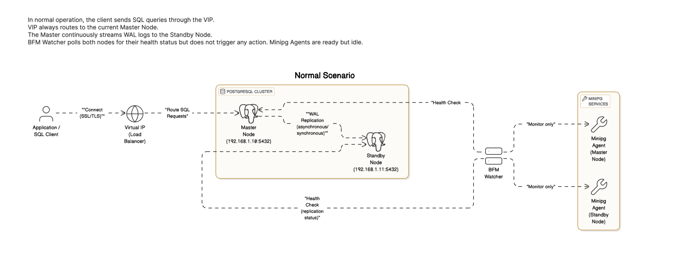
Figure 1: BFM Normal Scenario – In a healthy state, the master node streams WAL logs to the standby node, and the VIP always routes SQL requests to the master. BFM only monitors health status.
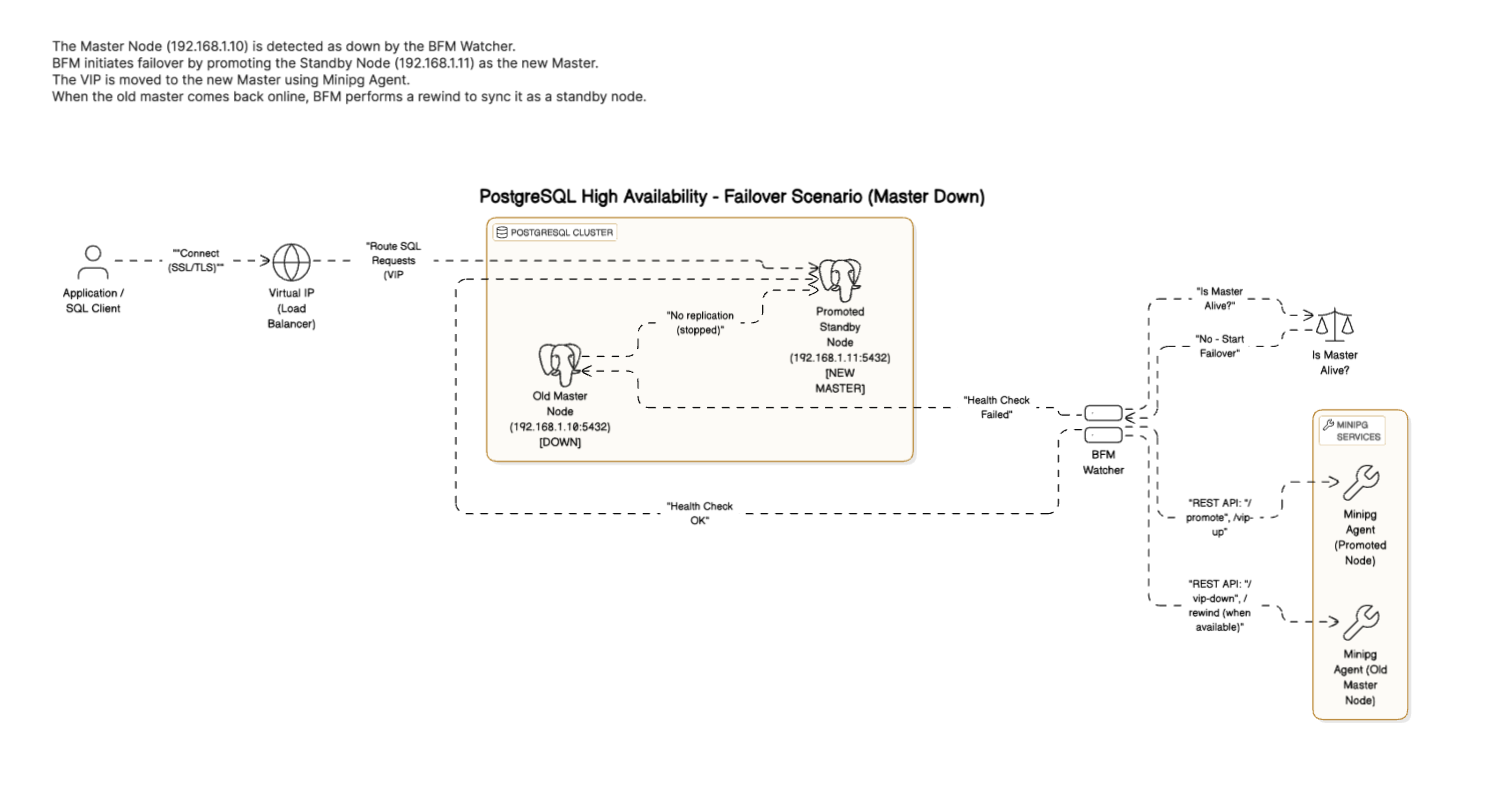
Figure 2: BFM Failover Scenario – When the master node fails, BFM promotes the standby node to master, redirects the VIP, and reconfigures the old master as a standby after recovery.
Component Roles
BFM Watcher: Continuously monitors the health of PostgreSQL nodes by tracking heartbeat signals. If a node fails to respond, it triggers the failover sequence.
API Server: Handles management requests and provides system status updates. It also plays a key role in deciding which standby node should be promoted during a failover, offering a set of RESTful endpoints for administration.
VIP Manager: Manages the Virtual IP (VIP) during failover, ensuring that applications remain continuously connected by redirecting the VIP to the new primary node.
PostgreSQL Nodes: Represent the data servers. Typically, one node acts as the primary (master) while the others serve as backups (standby) that can be promoted if failure is detected.